

Application Example of Optically Isolated Probe in Double Pulse Testing of Motor Controllers
Case Introduction
Double pulse testing enables engineers to accurately evaluate key performance parameters of power devices used in motor controllers, including switching speed, switching loss, voltage behavior, and current characteristics. These insights are essential for optimizing controller design and improving overall system efficiency.
However, measuring the upper switch gate-source voltage (Vgs) during a double pulse test presents a significant technical challenge. The measurement system must not only offer wide bandwidth to capture fast switching transitions, but also deliver exceptionally high common-mode rejection capability to suppress interference generated during high-speed operation.
Test Example
Device Under Test:
Core control board of a new energy vehicle motor controller
Test Points:
Upper switch Vgs and upper switch Vds within the motor controller bridge circuit
Customer Challenge:
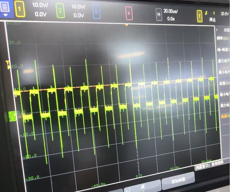
When traditional differential probes were previously used to measure the upper switch Vgs, severe signal oscillations were observed. These distortions made it extremely difficult to analyze waveforms accurately or identify the root cause of circuit issues.

Test Site
The on-site test setup included Micsig’s high-resolution oscilloscope (MHO3 Series – MHO3-5004), an optically isolated probe (MOIP Series – MOIP1000P), a high-voltage differential probe (DP1502), and the device under test.
During the double pulse test, the optical isolation probe was used to measure the upper switch Vgs. This portion of the motor controller represents the core switching module and operates at extremely high speeds, often within the nanosecond range. Under such conditions, intense electromagnetic interference (EMI) is generated due to rapid voltage and current transitions.
The high common-mode rejection ratio (CMRR) of the optical isolation probe effectively suppresses this interference, allowing the true waveform characteristics to be revealed. Even in environments with strong EMI, the probe delivers clean, stable voltage signals.
In comparison, the interference affecting the lower switch is relatively weaker, allowing differential probes to meet measurement requirements in that part of the circuit. Currently, most double pulse tests rely on differential probes with approximately 200 MHz bandwidth and 1500 V isolation.
Because the chip pins of power devices are often very thin, conventional contact-based current measurement methods may not be suitable. To address this, a Rogowski coil is recommended for measuring the lower switch drain current (Id). As a non-contact current measurement solution, the Rogowski coil enables accurate current capture without physically stressing or damaging delicate device pins, while also simplifying test setup.
The actual measured waveforms are shown below: the optical isolation probe measures the upper switch Vgs, the differential probe captures the lower switch Vds and Vgs, and Micsig’s Rogowski coil RCP1200XS is recommended for measuring the lower switch Id.

Customer Feedback
In previous double pulse testing, the upper switch Vgs signal exhibited significant common-mode interference. Due to limited understanding of CMRR performance in differential probes, the initial test results were trusted without question. The observed oscillations were assumed to originate from the system design itself, leading to repeated circuit modifications and validation efforts—yet the issue remained unresolved.
After switching to Micsig’s optically isolated probe, the measurement quality improved dramatically. The probe maintained a high CMRR even in the high-frequency range, and the oscillations previously observed in the waveform disappeared. The captured signals closely matched theoretical expectations and simulation results, confirming the true behavior of the circuit.
About Micsig Shenzhen Micsig Technology Co., Ltd.
is a leading manufacturer and solution provider specializing in signal testing and measurement equipment. As a recognized national high-tech enterprise and innovation-driven company, Micsig is dedicated to advancing cutting-edge measurement technologies. With a strong focus on oscilloscopes and oscilloscope probes, Micsig has consistently remained at the forefront of industry innovation. The company is recognized as a pioneer in flat-panel oscilloscopes and a market leader in optical isolation probe technology. Guided by professionalism and a clear mission, Micsig continuously pushes the boundaries of technology to help engineers and businesses achieve greater efficiency and performance. Every innovation reflects the commitment to exploring new possibilities and helping to shape future trends in electronic measurement technology.
Conclusion
The MOIP1000P optical isolation probe from Micsig delivers an ultra-high common-mode rejection ratio of up to 180 dB, while still maintaining greater than 100 dB CMRR at 1 GHz bandwidth. This outstanding performance enables highly accurate and reliable testing and validation of circuits built around SiC and GaN power devices.
By accurately capturing the real upper switch Vgs voltage waveform, engineers can confidently assess whether motor controller designs meet performance requirements, ensuring both high efficiency and long-term reliability in new energy vehicle applications.
Related articles

Application of Micsig SigOFiT Optical-Fiber Isolated Probe
Using Optically Isolated Probes to Test High-Power DC Power Supplies
A Common Misunderstanding About Optical-Fiber Isolated Probes
Application Example of Optically Isolated Probe in Double Pulse Testing of New Energy Vehicle Motor Controllers
Fibre optic insulated probe during the double pulse test
Misunderstanding Signal Frequency in Power Device Bridge Circuits: Switching Frequency vs. Signal Bandwidth